By Olom, UJ; Agi,
JI; Ogbaje, H (2022).
|
Greener Journal of Science,
Engineering and Technological Research
ISSN: 2276-7835
Vol. 11(1), pp. 1-13, 2022
Copyright ©2022, the copyright of
this article is retained by the author(s)
https://gjournals.org/GJSETR
|

|
Design
and Fabrication of a Manually Operated Corn Planter with Fertilizer Applicator
Olom U. J.1, Agi
J. I.2 and Ogbaje H.3*
1Department of
Agricultural and Environmental Engineering, Joseph Sarwuam
Tarka University, Makurdi,
Nigeria
2,3 Department
of Agricultural and Bio-Environmental Engineering Technology, Kogi State Polytechnic, (Itakpe
Campus), Nigeria.
E-mails: Jacobagi469@ gmail.
com2, hopeogbaje@ gmail. com3
|
ARTICLE INFO
|
ABSTRACT
|
|
Article No.: 111922096
Type: Research
Full Text: PDF, HTML, PHP, EPUB
|
A manually
operated corn planter with fertilizer applicator was designed and
constructed to plant maize crops. The planting machine is made up of a
seed/fertilizer hopper, furrow opener, front wheel, rear wheel, seed
discharge tube, furrow covering device, seed metering device, handle,
bearing, chain and sprockets. The machine’s field performance test for
planting maize shows that the planter was able to plant with adjustable
furrow opening depth and seed spacing. Average field seed planting space by
the metering unit was 34 cm. The average metering efficiency was 94.5 % at
machine speed of 0.6 m/s. The machine has a field capacity of 0.17 ha/hr and the field efficiency of 73.98 %. The seed rate of
the machine was 22.5kg/ha while the fertilizer rate was 74.6kg/ha. The seed
damage was found to be 2.45%. With good care and maintenance, the planter
would relief peasant farmers of the difficulties encountered in maize
production. The cost of fabricating the manually operated corn planter with
fertilizer applicator is ₦32,000.
|
|
Accepted: 19/11/2022
Published: 31/12/2022
|
|
*Corresponding Author
Ogbaje, H.
E-mail: hopeogbaje@ gmail.com
|
|
Keywords: Design, Fabrication, Manually operated, Corn planter,
Fertilizer applicator
|
|
|
|
1.
INTRODUCTION
For years, human power has been the
major power in agricultural production. The gradual replacement of human power
with mechanical devices or systems has brought a tremendous improvement to
agricultural yield. Agricultural mechanization has helped in agricultural
production, processing, storage and so on which has reduced drudgery, improve
timeliness of operation and efficiency of various farm operations, bringing
more lands under cultivation, preserve the quality of agricultural produce,
provide better rural living condition and markedly advance the economic growth
of the rural sector [1].
One of the major challenges faced by
the peasant farmers in Nigeria is the constraints experienced in seed planting
as a result of manual power usage. Most of these peasant farmers cannot afford
the money to procure or hire sophisticated machinery that can be used for their
planting operation. The cost of the
machine is going to be reduced by designing and constructing a simple planter/
fertilizer applicator to replace the bulky imported planters. The design of
this planter is simple and easy to fabricate. The size of the machine,
production cost, and transportation were reduced to the barest minimum. There
are several advantages of seed planter cum fertilizer applicator over the
traditional maize planting methods in the field. Those advantages include
uniform seed and fertilizer distribution, calculated quantities of seed and
fertilizer can be placed at the required depth with fertilizer below and besides
the seed [2].
The aim of this work was to develop a
simple mini corn planter/fertilizer applicator using locally available
materials at relatively low cost for peasant farmers and garden use.
2.
MATERIALS
AND METHODS
2.1 Materials Used for the Planter
The manually operated single row
planter for sowing seed and placement of fertilizer consists of the handles,
seed/fertilizer hopper, furrow opener, front wheels, seed discharge tube, furrow
covering device, and seed metering device, chain and sprockets.
2.2 Determination of the Engineering
Properties of Maize Seeds and Fertilizers
In the design of this seed planter,
the engineering properties of the maize seeds and fertilizers were put into
consideration to avoid seed damage and for proper placement of seeds and fertilizers
in the soil at the desired depth and compaction.
The determined properties are: moisture content, maize seed size and
shape, arithmetic and geometric mean diameters, sphericity, seeds weight, bulk and true
densities, porosity, the coefficient of friction and angle of repose.
2.3 Mode of Operation of the Planter
The
design and material selection was to ensure that the machine was easy to
construct, affordable for the target end users, with most of the components
made with locally available materials, and low technology requiring little or
no training for operation and maintenance. To operate the planter, seeds and
fertilizers were poured into their separate compartments in the hopper; the
planter is then positioned at the desired starting point, and pushed along the
row by means of the handle. About two seeds were picked up by the metering
plate and introduced into the chute. The furrow opener continuously opens the
furrow and the seeds metered into the chute falls into the opened furrow which
is then closed by the furrow closer. As the planter is pushed along the row, it
plants continuously at 30cm intra - row spacing, until the seeds in the hopper
gets finished to a level requiring refilling of the hopper. For the planting
operation, the hopper was filled with seeds. The filling of the hopper depends
on the area of the field to be covered. As the multi-crop planter was pushed
forward in the direction of travel, at an average speed of 0.6m/s, the pointed
bar type furrow opener penetrated the soil creating a furrow for seeds to be
placed.
2.4 Fabrication of the Planter
The planter was
fabricated and tested at Udeco Engineering Company
Limited, kilometer 4, Gboko road, Makurdi,
Benue State. All the parts of the maize planter were fabricated from mild steel
material, except for the seed tube which was made from plastic material. The
hopper was fabricated using 2 mm thick mild steel metal sheet. The main frame
which supports every other component of the planter was fabricated using 50 mm
angle bar of 4 mm thickness. The handle for the planter was fabricated using a
40 mm mild steel square pipe. The adjustable furrow opener and furrow closer
were both fabricated using a combination of 20 mm x 5 mm mild steel flat bar
and 20 mm rod. Plates 1 show the fabricated planter.
2.5 Machine Components and Design Analysis
a. Hopper design
The seed hopper assumes the shape of a
frustrum of a truncated pyramid with the dimensions
of 100 mm x100 mm at the bottom, 300 mm x 300 mm at the top and 300 mm height.
The angle of inclination of the hopper will be fixed at 300, which
is modestly higher than the average angle of repose of the seeds to ensure free
flow of seeds. The hopper is divided into two segments/compartments, the seed
segment and the fertilizer segment. The seed compartment is designed to
accommodate 2 kg of seeds while the fertilizer compartment accommodates 4 kg of
fertilizer. The hopper is made of light durable mild steel metal sheet of 3 mm
thick. Figure 1 shows a schematic representation of the hopper.

Figure
1: Schematic diagram of the hopper
The volume of hopper was gotten from the
mass of seeds/ fertilizers and their respective bulk densities.
The volume of seeds in the hopper was
calculated using equation 1.
 (1)
(1)
Where; V1 = Volume of seed
compartment (mm3), M1 = Mass of seeds and
 = bulk density of maize
seeds
= bulk density of maize
seeds
The volume of fertilizer in the hopper is
given as
 (2)
(2)
Where; V2 = Volume of
fertilizer compartment (mm3), M2 = Mass of fertilizers
and
 Bulk
density of fertilizer.
Bulk
density of fertilizer.
Total volume, VT (mm3)
= V1
+ V2
Total volume of hopper is determined = 97.7 105mm3
but the hopper will be
about 20% greater than VT
Hopper volume = Vh
(
The top area of the hopper A1is
given as
 (3)
(3)
The bottom area of the hopper A2is
given as
 (4)
(4)
Where; A1 = Top area of hopper
(mm2), a = Top length (mm).
A2
= Bottom area of hopper (mm2), and b = Bottom length (mm).
The height of the hopper, h is gotten from
equation 5
 (5)
(5)
The height of the hopper obtained is 483.3mm
b. The frame
The frame forms the platform on which
other components will be mounted. The materials used for the main frame was
selected on the basis of its strength and reliability from readily available
materials. In this work, mild steel angle iron of 50 mm by 50 mm by 4 mm
thickness was considered useful to give the required rigidity. Angle iron made
of carbon steel has high strength properties and is used for general
engineering purposes [3].
c. Seed chute
This is the channel through which
seeds are conveyed from the seed meter to the device that deposits the seed on
the soil surface or in the furrow. The seed chute is located on the outer part
of the hopper by the side on which the vertical seed plate is attached. The
material used for the design is a cylindrical funnel made of mild steel pipe
with a diameter of 30 mm in order to accommodate at least two seeds at a time.
d. Furrow opener
Furrow opener opens the soil where
seeds metered out through the chute will be dropped and covered. The type of
furrow opener used for this design is the adjustable ‘shovel type’ furrow
opener which gives a ‘v’ shaped furrow opening and is suitable because it cuts
and displaces the soil sideways for easy planting [4]. The material used for
the design of the furrow opener is mild steel angle bar because of its high
strength to withstand soil resistance.
e. Furrow coverer
The furrow closer was also designed to
be adjustable. It was designed to allow for proper covering and compaction of
the soil over the seeds in the furrows. The design of the
seed covering device on a planter depends on many factors, including: the soil
type and soil condition, the design of the furrow opener, and the speed of
operation, etc. [4]. The Furrow covering device was placed
perpendicular to the direction of travel of the machine to facilitate proper
covering of the soil.
f. The Front wheel
The front wheel was designed to
enhance free movement on loose soils. It is made of 6 mm thick mild steel flat
bar cut out into 80 mm width and folded into a circle of 360 mm diameter.
Pieces of metal rods were attached alternately throughout the circumference of
the wheel to provide lugs on its periphery which increase traction and reduce
slip. The front wheel provides drive for the metering mechanism through a chain
and sprocket system.
g. The rear wheel
The rear wheel is the driven wheel or
seed firming device. Seed firming devices are designed to press uncovered
seed into the soil at the base of the seed furrow to improve seed to soil
contact [4]. For
this design, a standard wheel size for equipment similar to wheel barrows with
the diameter of 200 mm as proposed by Murray et al [4] was adopted
on the basis of its strength to enhance stability and manoeuvrability during
operation.
h. The handle
The handle of the planter
was designed to meet the different height of operators which can be adjusted
accordingly to reduced drudgery. The handle helps the operator to push the planter
at the time of operation [5]. The length of the handle was calculated based on
average standing elbow height of an operator of 120cm. Distance of wheel centre from the operator in operating condition is 130cm.
So, the angle of inclination (θh) with the horizontal is
 (6)
(6)
Where:
a1= Height of centre of wheel to the elbow
and
a2 = Horizontal distance between
the normal to the centre of wheel and normal to the
elbow line.

Angle of inclination ( was
determined to be =
was
determined to be = 
i. Seed metering
mechanism
The metering mechanism is a major
component in a planter. It picks the required number of seeds and delivers them
into the soil through the chute at required depths created by furrow openers. Therefore,
the design considered the size of the seed, the intra and inter - row spacing
for each seed, which usually differs from one crop to another. According to
Murray et al. [4], seed plate thickness should be between the ranges of 3 mm to
6 mm to enable easy picking up of seeds and also to avoid damage of the seeds.
For the design of the seed metering device
the most important thing is that how many cells would be developed for desired
crop; so that the requirement of the plant to plant spacing is achieved. So
Number of cells on the seed metering device was obtained from equation 7 [6].
Number of cells =  (7)
(7)
Where: D = Diameter of ground wheel (m),
Z = Intra-row spacing (m) and I = Speed ratio.
No. of seed cell gotten = 1.2 ≈ 1
In this design, the metering mechanism was
made with plate of 116mm diameter and 3mm thickness with spaced cell near and
flushing with the circumference of the plate. The cell was designed to pick an
average of two maize seeds and drop them at intra row spacing of 30cm. The seed
cell measured 2 cm by 1.5 cm and 1.3 cm deep to accommodate two (2) to three
(3) seeds while the fertilizer cell measured 2.5 cm by 1.5 cm and 1.5 cm deep. The
seed cell was made adjustable in order to plant other seeds of different sizes.
The plate is attached vertically on a horizontal shaft driven by the front
wheel through a chain and sprockets transmission.
The weight of the metering plate, W is given
as
 (8)
(8)
Mass of plate was gotten by direct
weighting
Mass
of plate gotten = 1.3 Kg
Weight
of the metering plate W obtained = 12.75N
J. Weight of seeds and
fertilizers in the hopper
The
weight of the grain, Wg will be determined
using equation 9 [7]
The weight of the
seeds in the hopper is given as
 (9)
(9)
The weight of the
fertilizers in the hopper is given as
 (10)
(10)
Where; Wg=
Weight of seeds (kg), Wf = Weight of
fertilizers (kg).
Wg and Wf
gotten were 19.62N and 39.24N respectively
k. Design of chain
and sprockets
Chains are mainly used for
transmission of power from one shaft to another, when the distance between the
centres of shafts is short such as bicycles, agricultural machinery, rolling
mill etc. The chains are used for velocities up to 25 m/s and for power up to
110 kw [3]. The driving sprocket was designed with an
assumed speed of 65 r.p.m while smaller sprocket
(follower) moves at 180 r.p.m. Figure 2 shows an open
chain drive system connecting two sprockets.

Figure 2:
Sprockets and chain showing centre distance
The velocity ratio of a chain drive is giving
as.
V.R =  (11)
(11)
Where;
N1
= speed of rotation of smaller sprocket in r.p.m,
N2 = speed of rotation of larger sprocket in r.p.m,
T1 = Number of teeth on the smaller sprocket, T2 = Number
of teeth on the larger sprocket.
For this design, the smaller sprocket of
14 teeth was selected because of the low speed requirement. The number of teeth
on the larger sprocket is given as

 (12)
(12)
The service factor (Ks) is the
product of various factors K1, K2 and K3. The
values of these factors are given as follows [3]:
Load factor (K1) =1.25, for
variable load with mild shock, Lubrication factor (K2) = 1.5, for
periodic lubrication, and Rating factor (K3) = 1, for 8 hours per
day .
Therefore, service factor,
 (13)
(13)
The pitch circle diameter of the smaller
sprocket is given as,
 (14)
(14)
The pitch circle diameter of the larger
sprocket is given as,
 (15)
(15)
Where; d1 and d2 =
Pitch circle diameters the sprockets, and P = pitch of the chain in meter.
The average velocity of the smaller
sprocket is given by
V(m/s) =  (16)
(16)
Load on the chain, w is given by,
 (17)
(17)
 (18)
(18)
The minimum centre distance between the
two sprockets should be 30 – 50 times the pitch [3]. Taking the value of 35,

In order to accommodate initial sag in
the chain, the value of centre distance is reduced by 2 to 5 mm [3].
The number of links may be obtained from
equation 19 as
K =  (19)
(19)
The length of the chain is given by the
expression in equation 20

Length of Chain was = 1.778 m (20)
l. Maximum bending
moment on the shafts
The power delivered to the shaft by
some tangential force and the resultant torque (or twisting moment) set up
within the shaft permit the power to be transferred to various machines linked
up to the shaft in order to transfer the power from one shaft to another, the
various members such as sprockets, pulleys etc., are mounted on it. These
members along with the forces exerted upon them causes the shaft to bend [3].
Figure 3 show the load distribution on the driving shaft and metering shaft
respectively.
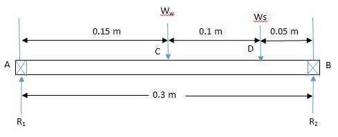
Figure 3:
Load distribution on the driving shaft
The maximum bending moment can be determined
from the following expressions:
From the principles equilibrium, the sum of
upward forces equals the sum of downward forces.
 (21)
(21)
Where;
R1
and R2 = reactions at both ends of the shaft,
Ww =  = weight of the
ground wheel,
= weight of the
ground wheel,
Ws =  weight of the
larger sprocket.
weight of the
larger sprocket.
M1 and M2 = weight of
the wheel and the larger sprocket respectively
The maximum bending moment of 2.75N-m is
chosen as the bending moment of the shaft
m. Diameter of the
driving shaft
Ø For the
driving shaft, the torque transmitted by the shaft is given in equation 22
below
 (22)
(22)
Where;
T = Torque
(N-m), p = Power transmitted(W) and N = Speed of
shaft(r.p.m).
The equivalent
twisting moment, Te is given in equation
34 [3].
 (23)
(23)
Where;
M = maximum bending moment on the shaft,
Km = shock and fatigue factor
for bending moment,
Kt = shock and fatigue
factor for torsional moment.
For the hollow shaft, the ratio of inside
to outside diameters is assumed to be 0.8.
The equivalent twisting moment
transmitted by the hollow shaft is given as
 (24)
(24)
Where; k = di/do
=0.8, di = inside diameter, do = outside diameter
For shafts without allowance for key ways,
the allowable stress, = 56N/mm2 [3].
The diameter of driving shaft was = 21 mm
n. Maximum bending
moment on the metering plate shaft
The maximum bending moment on the
metering shaft was determined from figure 4 below.

Figure 4: Load distribution on the
metering shaft
From the principles of equilibrium, the sum
of upward forces equals the sum of downward forces.
 25)
25)
Where;
R1 and R2 = reactions at both ends of the shaft,
Ww = = weight of the
metering plate
W2
= weight of the
smaller sprocket.
M1 and M2 = weight of
the metering plate and the smaller sprocket respectively
The maximum bending moment of 0.99 N-m is chosen
as the bending moment of the metering shaft plate shaft.
Ø The torque
transmitted by the metering shaft is given as
Ø
26)
Where;
T = Torque
(N-m), p = Power transmitted (W) and N = Speed of shaft (r.p.m).
The transmitted torque by the metering
shaft is = 39.58 N-m
The
equivalent twisting moment, Te is given as
 (27)
(27)
Where; M = maximum
bending moment on the shaft
 = 39608 N-mm
For the hollow shaft, the ratio of inside
to outside diameters is assumed as 0.8.
The equivalent twisting moment
transmitted by the hollow shaft is
(28)
Where; k = di/do
=0.5, di = inside diameter, do = outside diameter
 18.27 mm say 19 mm
 .
.
o. Design of Bearing
Bearings
are selected based on their load carrying capacity, life expectancy and
reliability. Ball bearings are fixed in the bushing provided at the two ends of
the frame in other to support the eccentric shaft on which the wheels are
attached. They allow the carrying of an impressive load without wear and tear and
with reduced friction. This device ensures the smooth operation of the wheels.
Life of a bearing is
the number of revolution which the bearing runs before the first evidence of
fatigue develops. For machines used for short periods such as hand tools, domestic
machines and agricultural machines, the life of bearings is given as 4000 to
8000 hours [3].
Let the life of the
bearing,  at the working speed of
65 r.p.m. The life of the bearing in revolution
corresponding to the reliability of 99% is gotten as
at the working speed of
65 r.p.m. The life of the bearing in revolution
corresponding to the reliability of 99% is gotten as
 (29)
(29)
Where; LH =
life of bearing (hours), N = speed (r.p.m) and L99
= life at 99% reliability
Let L90 =
life of the bearing (in revolutions) corresponding to 90% reliability
 (30)
(30)
Where; b = constant
=1.17
The bearings operate with
an equivalent load of 39.24N. The dynamic load rating of the bearing is given
as
 (31)
(31)
Where k = constant = 3
for ball bearing.
Where; C = Basic dynamic
load rating, and W = Equivalent load on bearing.
To select the most
suitable bearing, the dynamic load rating is multiplied by the service factor,
(KS) to get the load capacity. KS =1.5 for light shock
load [3].
p. Determination of the Maximum Draft on the
Planter
The maximum draft on the planter is a
function of the soils resistance on the machine and the area of contact of the
furrow opener with the soil. The maximum draft on the planter is the horizontal
component of push parallel to the line of motion in order to overcome the soil resistance
on the planter [8]. The maximum draft may therefore be obtained from the
following expression in equation 32.
 (32)
(32)
Where;
DFM = Maximum draft on the planter (N),
Afo = Surface
area of furrow opener in contact with soil (cm2), and
RS=
soil resistance (kg/cm2).
Afo = Recommended
depth of cut  width of furrow opener
(33)
width of furrow opener
(33)
The soil resistance, RS
for various soil types as given by Ikechukwu et al.
[9] are:
For sandy loamy
soils, RS = 0.210 kg/cm2, for silt loamy soils, RS
= 0.385 kg/cm2, and for clay loamy soil, RS = 0.455 kg/cm2.
Therefore, for
Sandy loamy soil = 20.6 N
Silt loam soil = 37.8 N
Clay loamy = 44.6 N.
Sandy loamy soil with the draft of 20.6 N
was used for the testing of this design.
2.6 Performance Evaluation on the Planter
The standard code by Mehta et al. [10]
for seed drill as reported by Bamgboye and Mofolasayo [11] was adopted in the evaluation of the
machine performance. Laboratory and field tests were conducted to determine the
performance of the machine. The machine was calibrated in the laboratory to
determine the rate of discharge, uniformity of seed spacing and seed damage
during operation.
Figures 5,
6 and 7 represent the pictorial view, sectional and exploded view of the
planter respectively while Plate 1 show the picture of the fabricated planter.

Figure
5: Pictorial View of the Planter

Figure 6:
Sectional View of the Planter

Figure 7:
Exploded View of the Planter

Plate 1:
The fabricated planter
Test for uniformity of seed spacing and seed damage
To determine the uniformity of seed
spacing, the hopper was loaded with grains and fertilizer and the machine run
within the length of about 10 m at walking speed, and the time of travel was recorded.
A measuring tape was used to measure the distance between successive drops of
seeds. This process was repeated five consecutive times and measurement of distance
between successive drops of seeds was recorded. The seeds discharged from the
seed tube during the run were observed for damage and recorded. The percentage
seed damage was calculated from equation 34 [7]
 (34)
(34)
% Seed damage
was = 2.43 %
Determination of field efficiency
To determine the field efficiency, the
planting operation was performed longitudinally with a constant forward speed
as determined by noting the distance of travel using measuring tape and
corresponding time to complete the distance with the aid of a stop watch. The
field efficiency of the planter will be calculated from equation (35) suggested
by kepner et al. [6]. An area of 90m2 was
used for the evaluation and it was covered in 196 seconds. The effective
operating time was 145 seconds while the idle time was 51 seconds.
 (35)
(35)
𝑤ℎ𝑒𝑟𝑒;  =𝐹𝑖𝑒𝑙𝑑𝑒𝑓𝑓𝑖𝑐𝑖𝑒𝑛𝑐𝑦 (%), 𝑇𝑒 = 𝑒𝑓𝑓𝑒𝑐𝑡𝑖𝑣𝑒 𝑜𝑝𝑒𝑟𝑎𝑡𝑖𝑛𝑔 𝑡𝑖𝑚𝑒 (𝑚𝑖𝑛) and 𝑇𝑡=𝑇𝑜𝑡𝑎𝑙𝑡𝑖𝑚𝑒 (min).
The total
time, Tt comprised of the
actual working time, time for turn at the end of the field, time for loading grains,
time for clog remover and resting time.
Field
efficiency determined = 73.98 %
Effective field capacity
The capacity of the planter may be
determined in terms of the area of land covered per hour during planting or the
number of seeds planted per hour of planting. The capacity of the planter in
terms of the area of land covered per hour was obtained from equation 36.
 (36)
(36)
Ca = Effective
field capacity of the planter in ha/hr
Time required to plant one hectare (1ha) of land is giving as

Metering efficiency
The machine was run over a distance of
10m and the total number of seed stand and the number of stand with no seeds
were recorded. The metering efficiency (ME) was computed from equation 37 [12].
 (37)
(37)
M.E obtained = 94.5%
Seed Rate per Hectare
The seed rate (kg/ha) was determined by placing the
planter on its stand with a container placed under the seed tube to collect
seeds and fertilizers by turning the drive wheel for 20 revolutions. The seed
and fertilizer rates were calculated.
Seed
rate (kg/ha) obtained 
Fertilizer rate (kg/ha) obtained = 74.6 kg/ha.
Cost
Analysis
The breakdown of the cost analysis for the fabrication of
the planter is given in Table 1 below.
Table
1. Cost of producing
the Planter.
|
S/No
|
Material
|
Quantity
|
Cost (₦)
|
|
1
|
Shaft
|
2
|
1,500
|
|
2
|
Mild
Steel Sheet Metal (3mm)
|
1
|
3,000
|
|
3
|
Bearings
|
2
|
3,000
|
|
4
|
Angle
Steel Bar
|
2
|
3,000
|
|
5
|
Square
pipe
|
1
|
2,500
|
|
6
|
Bolts
and Nuts
|
20
|
1,000
|
|
7
|
Chain
and Sprockets
|
1
set
|
2,000
|
|
8
|
Flat
bar
|
1
|
2,500
|
|
9
|
Paint
|
1
|
1,500
|
|
10
|
Labour
|
-
|
10,000
|
|
11
|
Transportation
|
-
|
2,500
|
|
|
Total
|
|
₦
32,500
|
3. RESULTS AND DISCUSSION
3.1 Results
The results obtained from the engineering properties
determinations of the seeds and fertilizers are presented in Table 2.
Table 3 shows the summary of the performance evaluation of the planter. As
shown in Table 4 the value of field efficiency obtained from the trials was
73.98%. Also, the effective field capacity of the planter was gotten as 0.17
ha/hr. The seed damage was found to be 2.45%. The metering efficiency for the
planter was obtained as 94.5%.
The mean length, width, and the thickness, of the maize seeds
were found to be 11.11 mm, 8.53 mm, and 4.85 mm while the sphericity,
arithmetic and geometric mean diameters, were found to be 69%, 7.71 mm and 8.16
respectively as shown in Table 2. The moisture content of the maize seeds was
found to be 8.5 %. The average 1000 seed weight was found to be 300 g. The
average bulk and true densities of the maize seeds at the moisture content of
8.5% were found to be 450.30 kg/m3 and 1120.87 kg/m3
respectively while the bulk and true densities of fertilizers were found to be
745 kg/m3and 1200 kg/m3 respectively. The porosity of
maize seeds was found to be 51.30 %. The angle of repose for maize seeds and
fertilizers were found to be 26.96o and 28.37o
respectively while the coefficient of friction for maize seeds and fertilizers
were determined as 0.38 and 0.26 as presented in table 2.
Table
2: Engineering Properties of Maize Seeds
and Fertilizers
|
Parameters
|
Unit
|
Maize
seeds
|
Fertilizers
|
|
Length
|
Mm
|
11.11
|
-
|
|
Width
|
Mm
|
8.53
|
-
|
|
Thickness
|
Mm
|
4.85
|
-
|
|
Geometric mean diameter
|
Mm
|
7.71
|
-
|
|
Arithmetic mean diameter
|
Mm
|
8.16
|
-
|
|
Sphericity
|
%
|
69
|
-
|
|
Moisture content
|
%
|
8.5
|
-
|
|
1000 mass
|
G
|
300
|
-
|
|
Bulk density
|
Kg/m3
|
450.3
|
745
|
|
True density
|
Kg/m3
|
1120.9
|
1200
|
|
Porosity
|
%
|
51.3
|
37.92
|
|
Angle of repose
|
o
|
26.96
|
28.37
|
|
Coefficient of friction
|
-
|
0.38
|
0.26
|
Table
3: Performance Evaluation on Planter
|
S/N
|
Parameters
|
Units
|
Mean
Values
|
|
1
|
Seed rate
|
Kg/ha
|
22.52
|
|
2
|
Fertilizer rate
|
Kg/ha
|
74.6
|
|
3
|
Seed damage
|
%
|
2.45
|
|
4
|
Field efficiency
|
%
|
73.98
|
|
5
|
Effective field capacity
|
ha/hr
|
0.17
|
|
6
|
Metering efficiency
|
%
|
94.5
|
|
7
|
Seed spacing
|
Cm
|
34
|
|
8
|
Planting depth
|
Cm
|
2.76
|
Table 4:
Field Efficiency and Field Capacity
|
Trial activity
|
Time for 90 m2
(s)
|
Time to plant one
hectare (hrs.)
|
|
Turning
at field end, removal of clogs, rest and refilling.
|
51
|
1.57
|
|
Actual
planting time
|
145
|
4.48
|
|
Total
time
|
196
|
6.05
|
|
Field
efficiency = 73.98%
Field
capacity =0.17 ha/hr
|
|
|
3.2 DISCUSSION
As shown in Table 4 the value of field efficiency
obtained from the trials was 73.98%. This shows a good and satisfactory
performance as it was within the range of values obtained for planting operation
by Olajide and Manuwa [13]
which was 71%. Also, the effective field capacity of the planter was 0.17
ha/hr. This is higher than that of the single row maize planter with a capacity
of 0.048 ha/hr developed by Ikechukwu
et al. [9]. This satisfactory result is due to its maneuverability which saves
time in moving and turning the planter from one point to another.
From the results obtained from the calibration of the
planter, it was observed that at lower speed (25 rev/min), the weight of seeds
discharged was 43g which is higher than that of higher speed (30 rev/min) with
a discharge of 39g while fertilizer discharge was 140g at 25 rev/min and 110g
at 30 rev/min. The planter effectively metered out two seeds per hole on the
average. This was satisfactory performance and the design was such that the
number of seeds metered out could be regulated by using adjustable
seed/fertilizer cells.
The average percentage of seed damaged of was 2.45%. The observed low
average value of percentage seed damage of 2.45% observed in this work is due
to minimal clearance between the metering device and its housing. The mean
depth of furrow opened at the medium setting of the opener was 2.76 cm. The
distance between successive seeds of 34cm was obtained.
4. CONCLUSION
The engineering properties of maize
seeds and fertilizers relevant for the design of this planter were all
determined. The manually-operated corn planter with fertilizer
applicator for the needs of small holder farmers has been designed, fabricated
and its performance evaluated. The machine has an overall field capacity of
0.17 ha/hr with average intra-row seed spacing of 34
cm and the field efficiency of the planter was 73.98 %.The planter was able to
effectively meter a maximum of two to three seeds per hole with minimum damage
of 2.45% to the seeds.The metering efficiency obtained was 94.48%
with a seed rate of 22.5 kg/ha and fertilizer rate of 74.6 kg/ha. With these
features, the manually operated corn planter cum fertilizer applicator will relief peasant farmers of the difficulties encountered in maize
production at a very low cost.
REFERENCES
[1] Onwualu A.P, Akubuo C.O and Ahaneku I.E, (2006).Fundamentals of Engineering for
Agriculture. Immaculate Publication Limited, Enugu, Nigeria.
[2] Ahmad, N., Abdul G., Anjum
M., and Muhammad, I. (2014).Design Modification and Field Performance of Two
Row Maize Planter. International Journal of Development Research, 4(7):
1336-1340.
[3] Khurmi, R.S. and
Gupta, J.K. (2005).A Textbook of Machine Design.Eurasia
Publishing House (Pvt.) Ltd., Ram Nagar, New
Delhi-110055, India.
[4] Murray, J.R., Tullberg,
J. and Basnet, B.B. (2006). Planters and their
Components; Types, Attributes, Functional Requirements, Classification and
Description. Australian Centre for International Agricultural Research (ACIAR),
Monograph 121, 2006.
[5] Sharma, D.N. and S. Mukesh (2010).Farm Machinery Design Principles and
Problems.2ndrevised edition Jain brothers, New Delhi.
[6] Kepner, B. A.,Bainer, R. and Barger, E. L., (1978).Principles of Farm
Machinery.3rd Edition.West port.G; AVI Publishing Company Inc.
[7] Ani, O.A, Uzoejinwa, B. B. and Anochili, N.
F. (2016).Design, Construction and Evaluation of a Vertical Plate Maize Seed
Planter for Gardens and Small Holder Farmers. Nigerian Journal of Technology
(NIJOTECH), 35(3): 647-655.
[8] Gbabo, A,
(1988).Design and construction of a two-row cowpea and maize planter.
Maintenance and Repair Unit, Agricultural Engineering Section, National Cereals
Research Institute, Badeggi
[9] Ikechukwu, I.B, Gbabo, A and Ugwoke, I.C.
(2014).Design and Fabrication of a Single Row Maize Planter for Garden Use.
Journal of Advancement in Engineering Technology, 2(1): 1-7.
[10] Mehta, M.L; Verma, S.R; Misra, S.K; and
Sharma, V.K.,(1995).Testing and Evaluation of
Agricultural machinery.National Agricultural
Technology Information Centre, India. PP 68-79.
[11] Bamgboye, A.I and Mofolasayo, A.S. (2006).Performance Evaluation of a Two-Row
Okra Planter. Agricultural Engineering International: the CIGR E-journal. Manuscript PM 06002.Vol. viii. July
[12] Bashiri, M., Ode, D.
A., and Ogwuche, E. U. (2013).Development of a Hand
Planter. Journal of Research in National
Development (JORIND), 11(2): 1-6.
[13] Olajide, O.G. and Manuwa, S.I. (2014).Design, Fabrication and Testing of a
Low-cost Row-Crop Planter for Peasant Farmers.Proceedings
of the International Soil Tillage Research Organization (ISTRO) Nigeria
Symposium, Akure, 3 (6): 94–100.
|
Cite this Article: Olom, UJ; Agi, JI; Ogbaje, H (2022).
Design and Fabrication of a Manually Operated Corn Planter with Fertilizer
Applicator. Greener Journal of Science,
Engineering and Technological Research, 11(1): 1-13.
|